MCU Timer-Driven Audio Generation
Introduction
In this lab, I learned how to use my MCU to play music by using timers. These timers generated square waves by toggling a GPIO pin at a specific frequency for specified durations. This lab also served as an introduction to working with the STM32 microcontroller boards. I gained a lot of experience with reading proper documentation (reference manual and datasheet) to understand clocks, timers, register, I/O, and more. The end result consisted of playing “Fur Elise” and my chosen song of “Hedwig’s Theme” from Harry Potter!
Design and Testing
Writing the Library in C
I used the Timer 15 and Timer 16 registers in order to output a square wave signal from the microcontroller. For this lab, we had to read the datasheet carefully and write our own library in C from scratch. One of the reasons I chose Timers 15 and 16 is because they have the same register map. This meant I could take advantage of only having to write one struct in my timer header file. Another reason I chose these timers is that they both have the ability to be configured to a PWM mode and be connected to a GPIO pin in alternate function mode in order to have the desired functionality of producing a square wave output.
After writing my header file, I wrote my timer source code, which consisted of four functions: initTIM to initialize my timer, delay_millis to provide a millisecond delay to set my note durations, initPWM to initialize the PWM mode of Timer 16, and setFreq to set the square wave to the desired frequency. Writing these four functions was the most difficult part of the lab, as they consisted of hours reading the reference manual to understand configuration, registers, and precisely which bits to set in which order to produce the desired functionality.
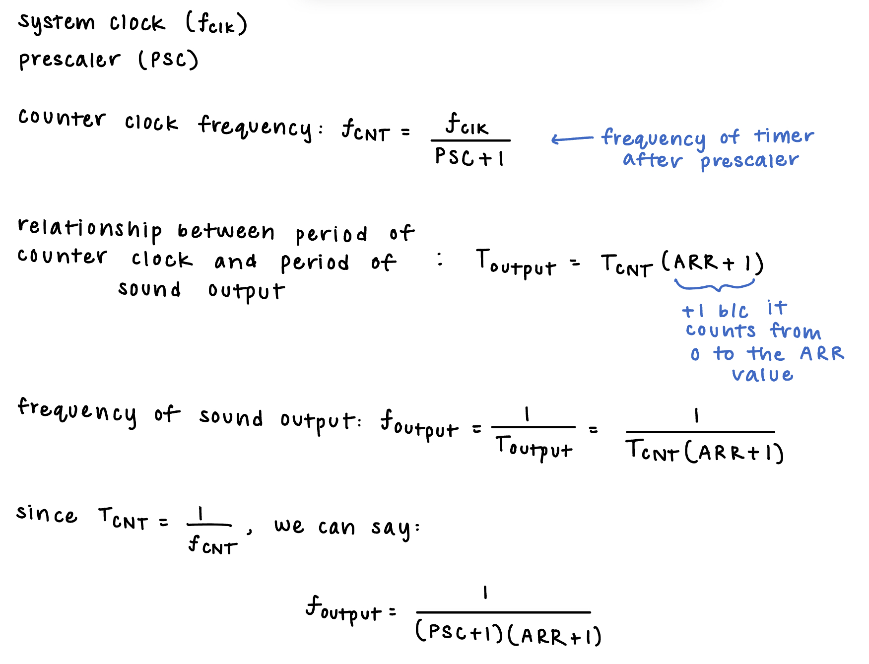
Software and Timing Calculations
To go into more details on how the timers work, the timer configured in the PWM mode had the auto reload register (ARR) and the capture/compare register (CCR1) set in order to produce a specific period and duty cycle. The ARR value is set such that when the counter is equal to this value, it resets to 0, meaning this value sets the period of the signal. When the counter is less than the CCR1 value, it outputs a low (0), and when the counter is higher, it outputs a high (1), meaning the CCR1 value sets teh duty cycle. I set the CCR1 value to be half of the ARR value to have a duty cycle of 0.5. For the timer configured to set the delay, I utilized the ARR to control the delay, as it was set depending on the millisecond input.
In this lab, I used a phase-locked-loop (PLL) to set the microcontroller clock at 80 MHz, and to produce lower frequencies, I used prescalers. The timing calculations and theory behind my prescaler values are shown below in Figure 1.
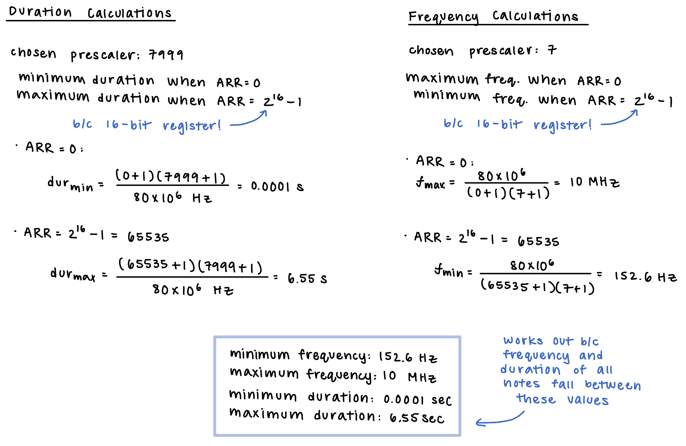
In order to make sure that the minimum and maximum frequency and duration were supported with my chosen prescaler values, I did the calculations shown below in Figure 2.
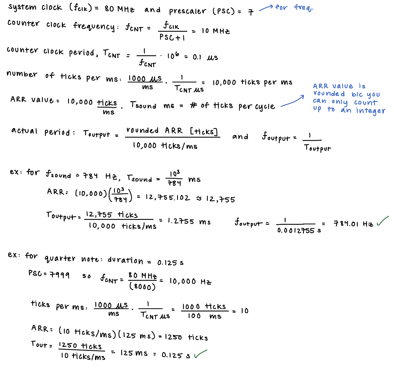
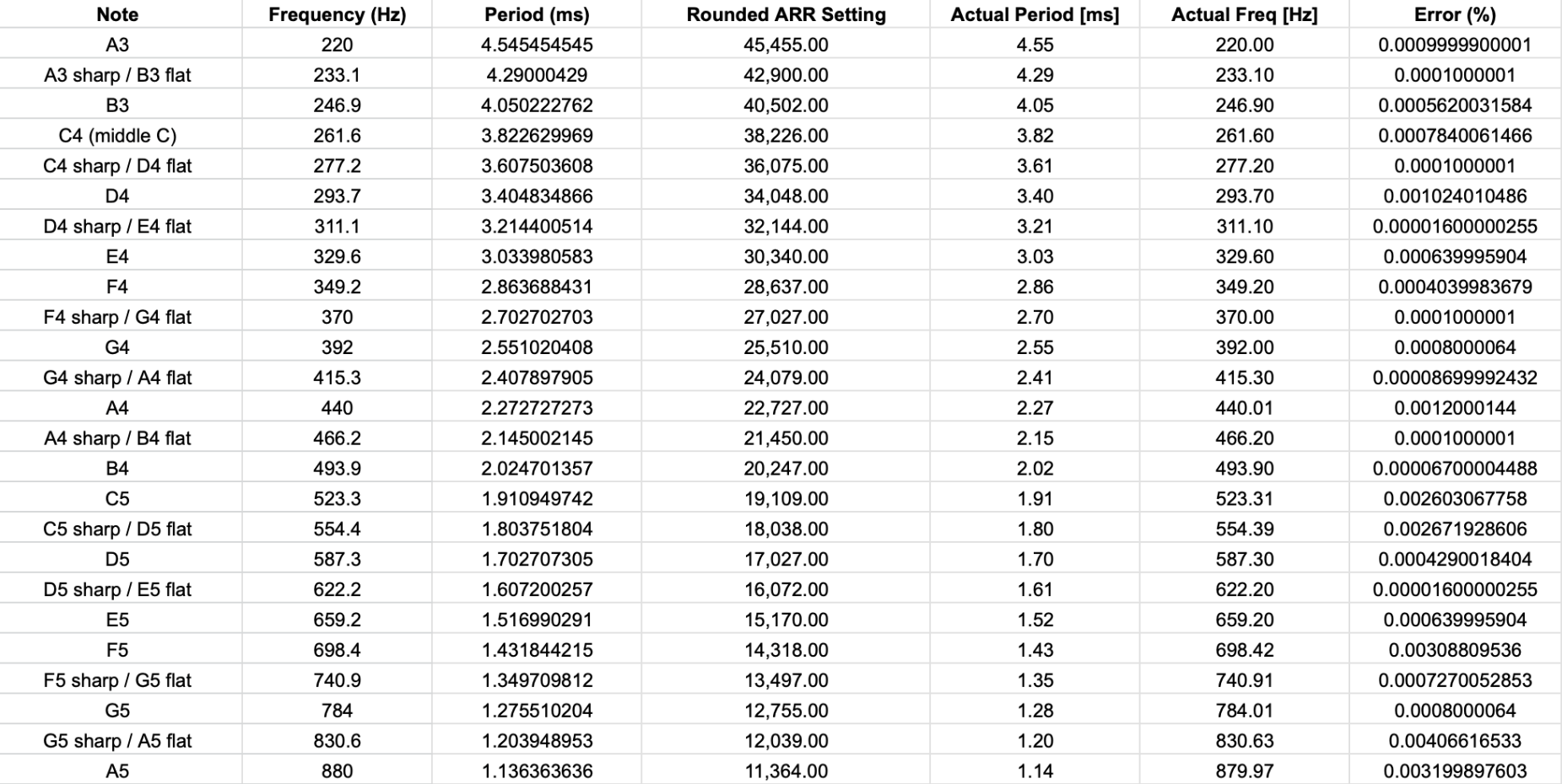
One of the specs for this lab was to produce individual pitches calculated to be accurate within 1% across the frequency range of 220-1000 Hz. Using the derived formula in figure 1 and careful unit conversion, I ran a timing analysis across this frequency range to make sure the spec was met. The calculations used to program the spreadsheet, showing examples of the pitches and durations being correct, as well as the resulting data is shown below in Figure 3 and 4, respectively.
Software Testing
In order to test the software’s functionality first, I uploaded the code to my MCU and used an oscilloscope to read the values of the GPIO pin to check that I was seeing the correct duty cycle and frequency. There was a lot of troubleshooting here, as I originlly did not see any square waves. I used Segger’s built in Debug mode to step through my code and ensure that all my registers were getting the value they were supposed to. After debugging and changing the way I configured/enabled things in my code, I started to see the correct frequency square waves in the oscilloscope.
Technical Documentation
The source code for the project can be found in the associated Github repository.
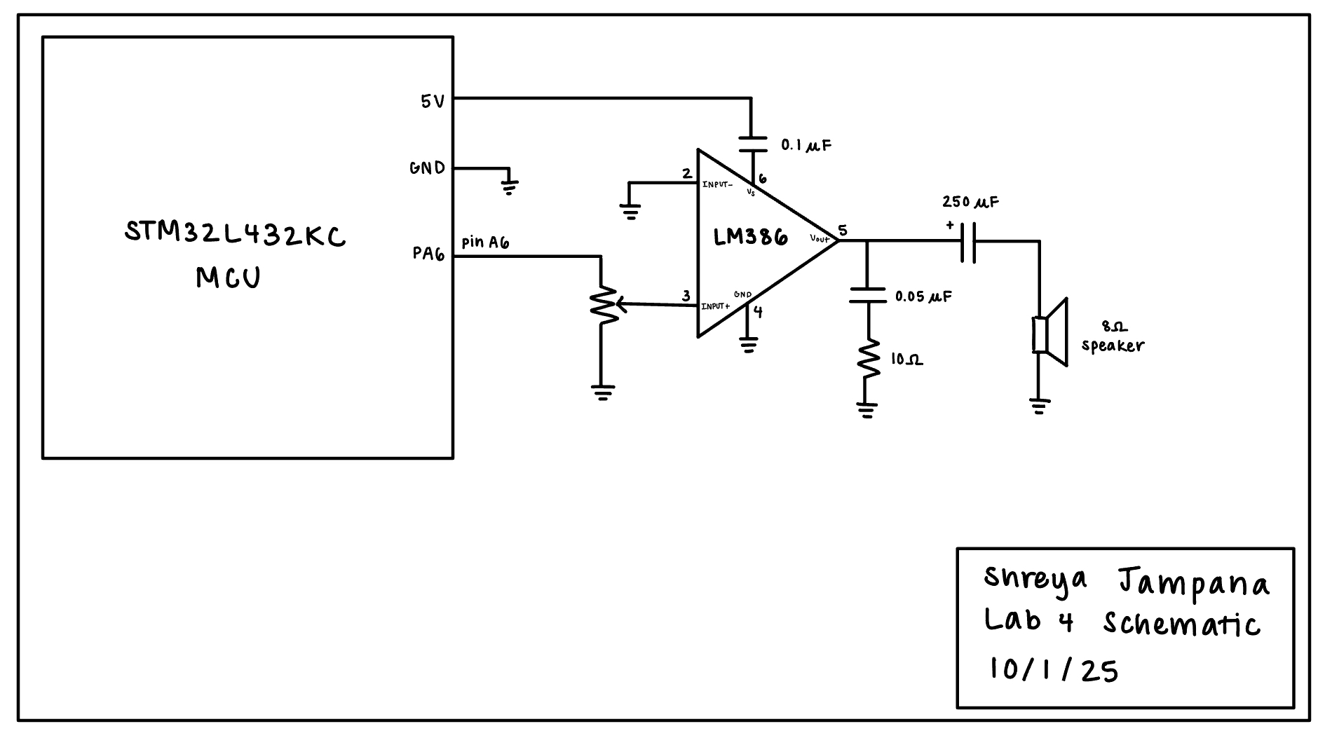
Schematic
The circuit for this lab was simple. It contained an LM386 audio amplifier to drive the 8 ohm speaker and a potentiometer for volume control. The schematic is shown below in Figure 5.
Results and Discussion
The design met all the intended objectives. The hardware for this lab, which was tested after making sure the software worked properly, worked on the first try. To encode a new song, I found the site music for music from Harry Potter, and transcribed the notes into frequencies using the table from the class website. A video of the final result, including Fur Elise and Hedwig’s Theme from Harry Potter, is shown below.
Conclusion
I was successfully able to use my MCU to play music in this lab! The learning curve was steep, as this was my first time writing libraries in C and using a microcontroller in depth. However, I got really comfortable reading the datasheet and reference manual, and I gained a better understanding of the STM32 overall.