MCU Interrupt-Driven Quadrature Encoder Speed Measurement
Introduction
In this lab, we used our MCU to determine the speed of a motor by reading from a quadrature encoder. Lab 4 helped me get familiarized with the microcontroller and working with documentation, and this time, we tackled another aspect of microcontrollers: interrupts. Using these, I was able to process real-time, fast changes and record accurate measurements.
Design and Testing
Quadrature Encoder Background
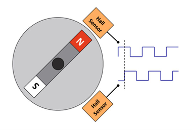
An encoder is a sensor that converts physical motion into electrical signals. A quadrature encoder is a common type of encoder that is used to measure the relative or absolute angle of a motor. They do this with the use of a patterned disk that is attached to the motor and spins with the motor. As shown in Figure 1 below, two stationary digital sensors 90 degrees out of phase are placed to produce two square waves that are 90 degrees out of phase with each other. The encoders used in this lab use magnets and hall effect sensors to produce the square waves. Using this theory and understanding, I designed my system to take full advantage of both signals to get the highest resolution measurement of the speed of the motor.
Interrupt Design
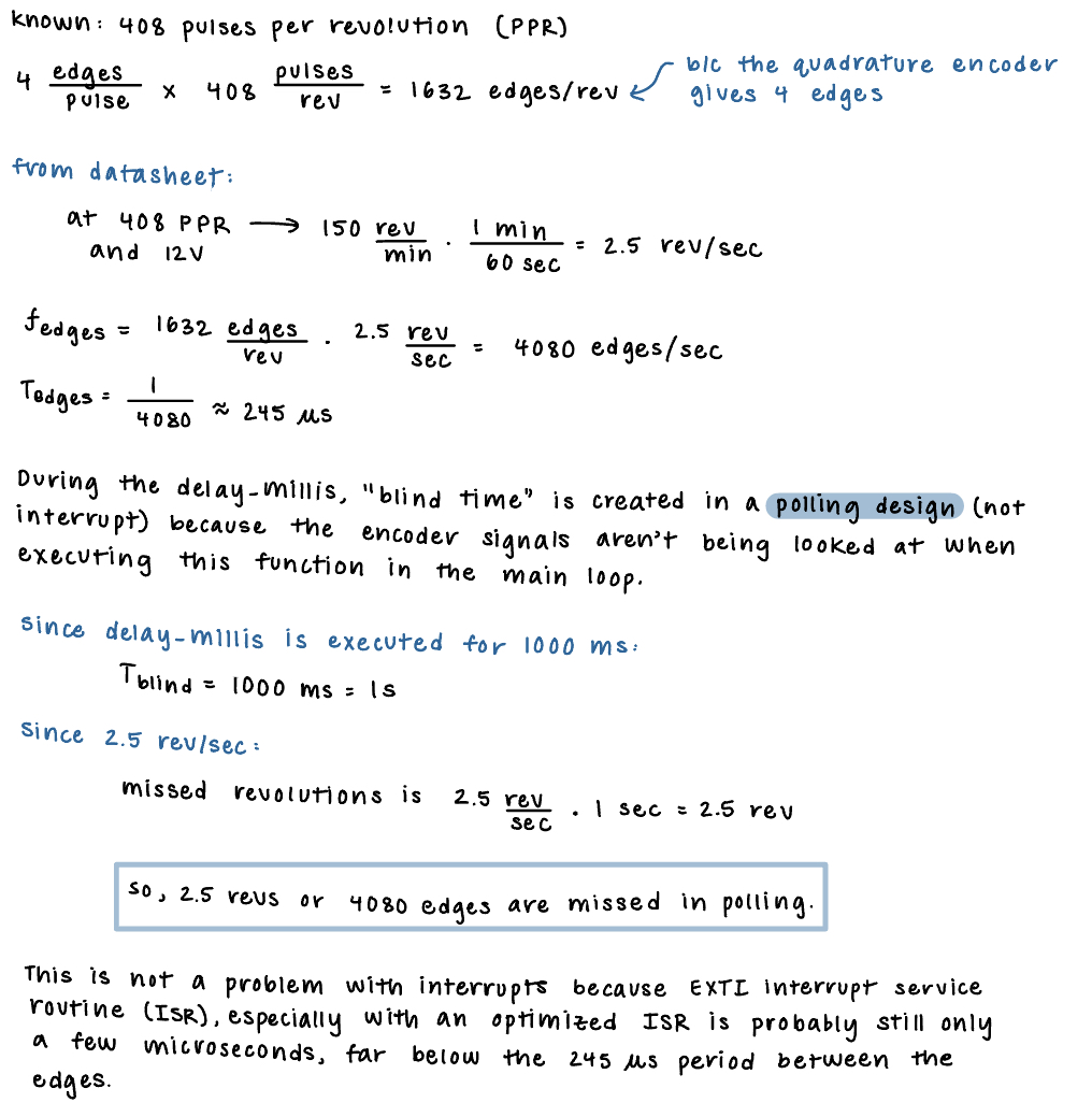
In order to check the signals from the encoder and measure the speed of the motor, I used interrupts instead of polling. Polling involves continuously checking the status of the GPIO pins to detect whether or not the encoder output changed. This means the speed of taking a measurement is dependent on the time it takes all the commmands in the while loop to execute. This is problematic because if the code in the main loop is executing of a delay is being executed, you could miss the signal coming from the GPIO pin. This can cause timing issues and lead to inaccurate motor speeds being recorded due to sampling not happening fast/accurately enough. This problem can be overrided by using interrupts. Interrupts are event-driven instead of time-driven. This means that when the interrupt goes high, the CPU jumps to that address and the main/current execution context is paused as the interrupt is executed. After it’s done, it returns back to the main code and continues where it left off. By doing this, interrupts give immediate attention to signal changes and ensure that all measurements are registered and correspond exactly to encoder changes. Some math to back up this understanding is shown below in Figure 2.
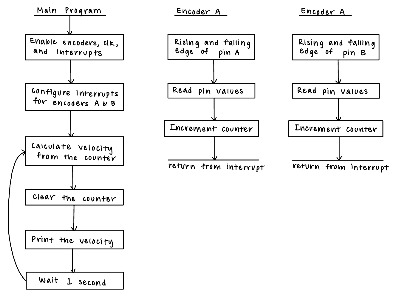
In order to achieve the highest resolution measurement, I used all edges of the encoder pulses. I did this by using two interrupts, one for Encoder A and one for Encoder B. Each encoder checked for the following four cases: clockwise rising edge, counter-clockwise rising edge, clockwise falling edge, and counter-clockwise falling edge. A counter was also used, which is explained more in the next section. The main steps of the program and the function calls are shown below in the flowchart in Figure 3.
Software and Calculations
The interrupt design, described above, was the main portion of the software. Another important part was incorporating the counter into the interrupt and using that to calculate velocity. As mentioned above, each interrupt had four cases. In each case, if the motion was clockwise, the counter incremented. If the motion was counter-clockwise, the counter decreased. A graphical illustration of this using the signals from the encoder are shown below in Figure 4.
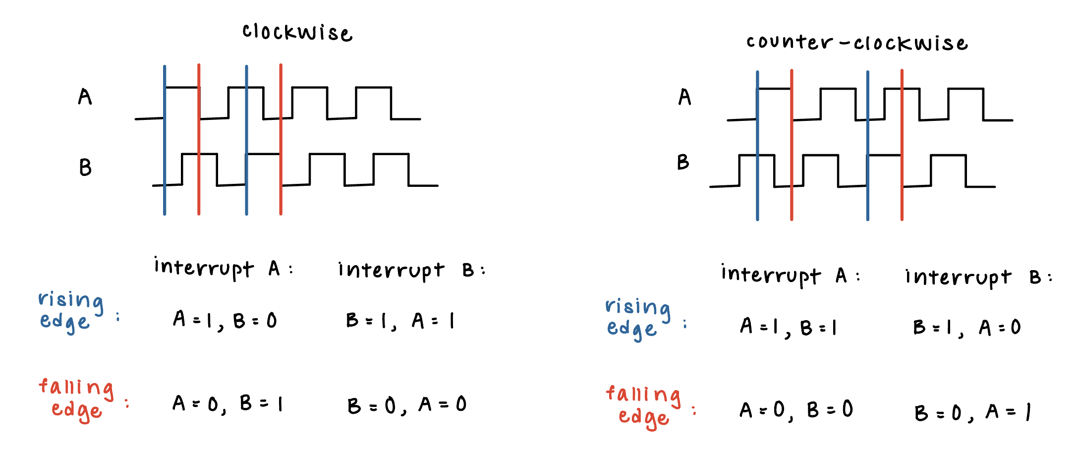
The following equation was used to determine the speed of the motor based on the counter: velocity = counter / (PPR * 4).
Verification
In order to make sure the measured speed matches the true motor speed and direction, I calculated the theoretical speed of the motor, hooked my motor up to the oscilloscope, and checked this against the values that my code output. From the datasheet, we know that at 12 V and 408 PPR, the speed of the motor should be 2.5 revolutions per second. Connecting the motor to the oscilloscope, I saw the following output, as shown in Figure 5.
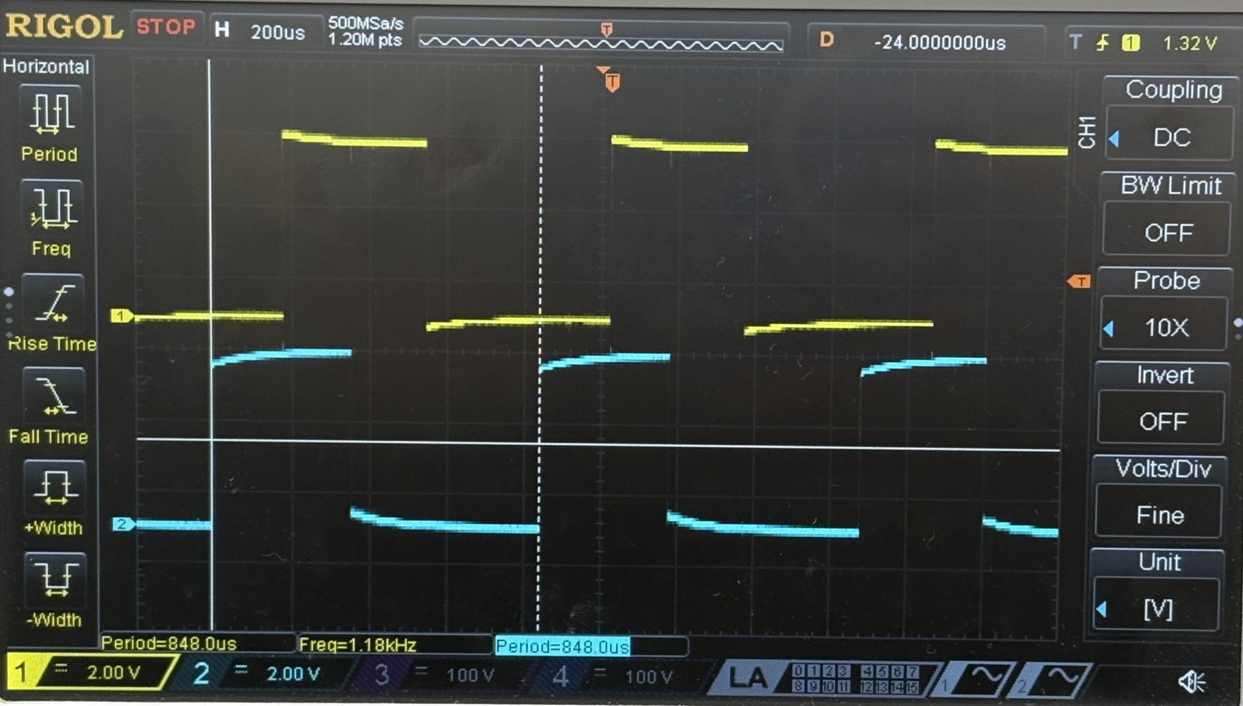
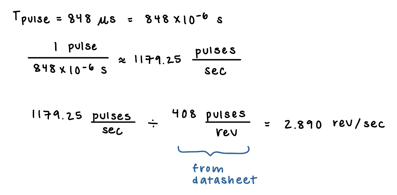
As shown on the oscilloscope screen, the output signal has a period of 848us. Calculations are shown below in Figure 6 to derive the speed of the motor using this value.
At this same voltage, the following speed of motor was output from my code, with each measurement being taken one second apart.
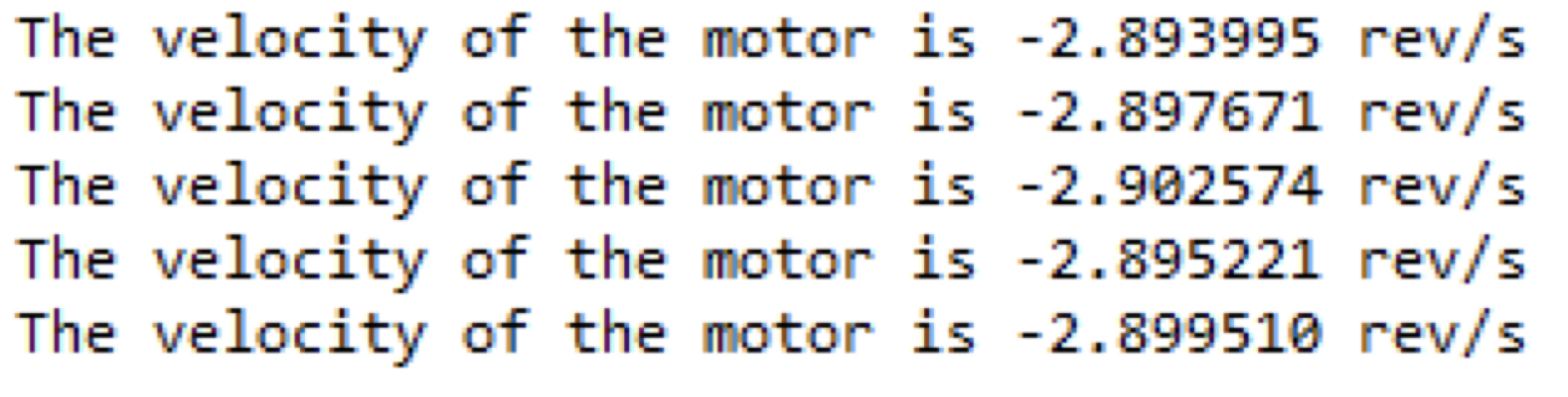
All of these calculations are close to each other. The variation between the speed of the motor from the oscilloscope and that from the code is very small, and could be due to the motor speed itself fluctuating and not spinning at the same frequency. Also, signal capture on the oscilloscope can’t be verified, so it’s hard to determine if I’m capturing at the same rate on both the oscilloscope and on my console. Give this, I’m happy with the small variation and error rate between expected and measured.
Technical Documentation
The source code for the project can be found in the associated Github repository.
Schematic
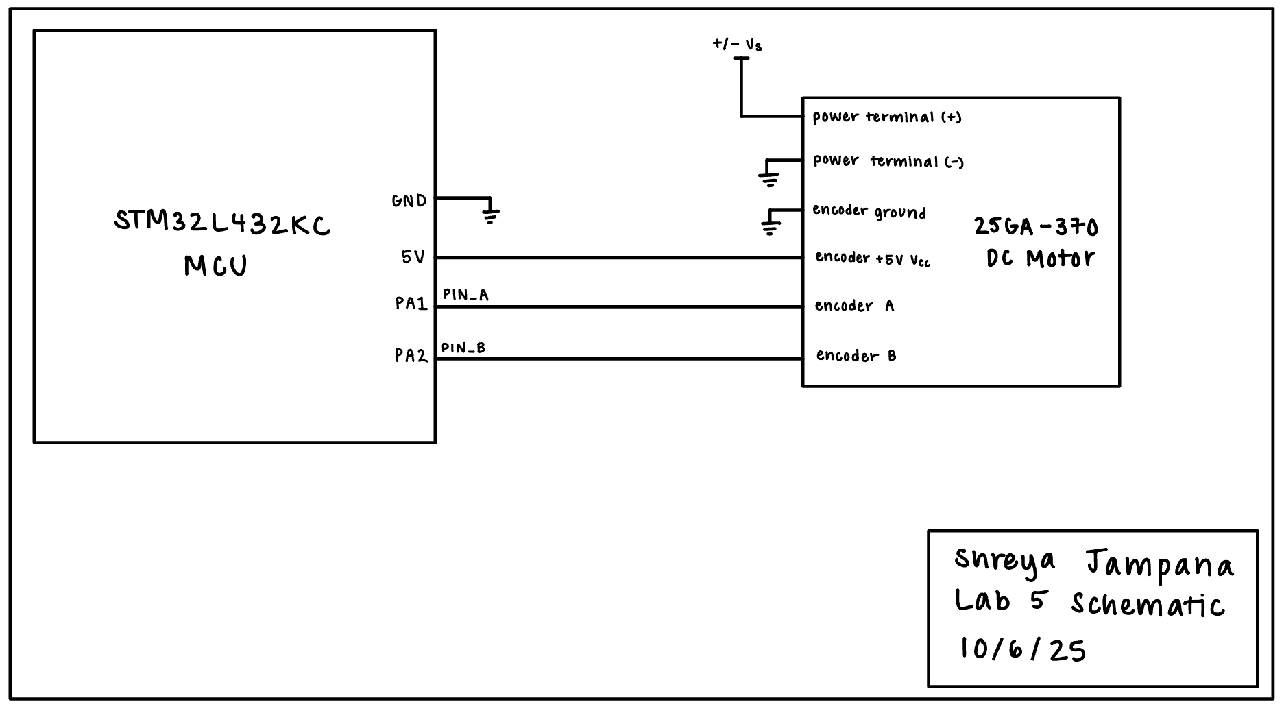
The circuit from this lab was very simple, as shown in the schematic below in Figure 8. It only consisted of connecting the motor encoder to the two MCU GPIO pins and a variable DC voltage +/- Vs being applied to the positive terminal of the motor from a power supply.
Results and Discussion
The design met all the intended objectives. After becoming comfortable with how to use the datasheet and reference manual for the MCU, this lab went by much smoother on the software end. The biggest point of confusion was understanding interrupts conceptually, but after that was done, the lab went by pretty smoothly. The final results are shown in the video below, with speed being output once per second on the console.
Conclusion
I gained even more experience with my MCU in this lab. Learning more about interrupts also taught me how to properly read and process fast changes in order to make the most accurate measurements.